A 0.42-Inch I2C OLED in Laboratory Instruments: What the -40 °C to 85 °C Rating, Emitter Aging and Supply Terms Really Cover
A 0.42-inch 72x40 OLED module with an I2C interface and an operating range of -40 °C to 85 °C is a credible front-panel display for laboratory instruments, but the temperature figure on its own does not tell you whether the instrument will still look and behave the same after ten years on a bench. Judge the part on three separate questions: how the range was verified, what actually wears out, and how long the module can be bought. Because the panel is emissive, the familiar backlight-lifetime conversation simply does not apply, which changes the failure modes you should be modelling. The useful work is to convert every vendor claim into either a test you can run or a clause you can write into the purchase order.
Key takeaways
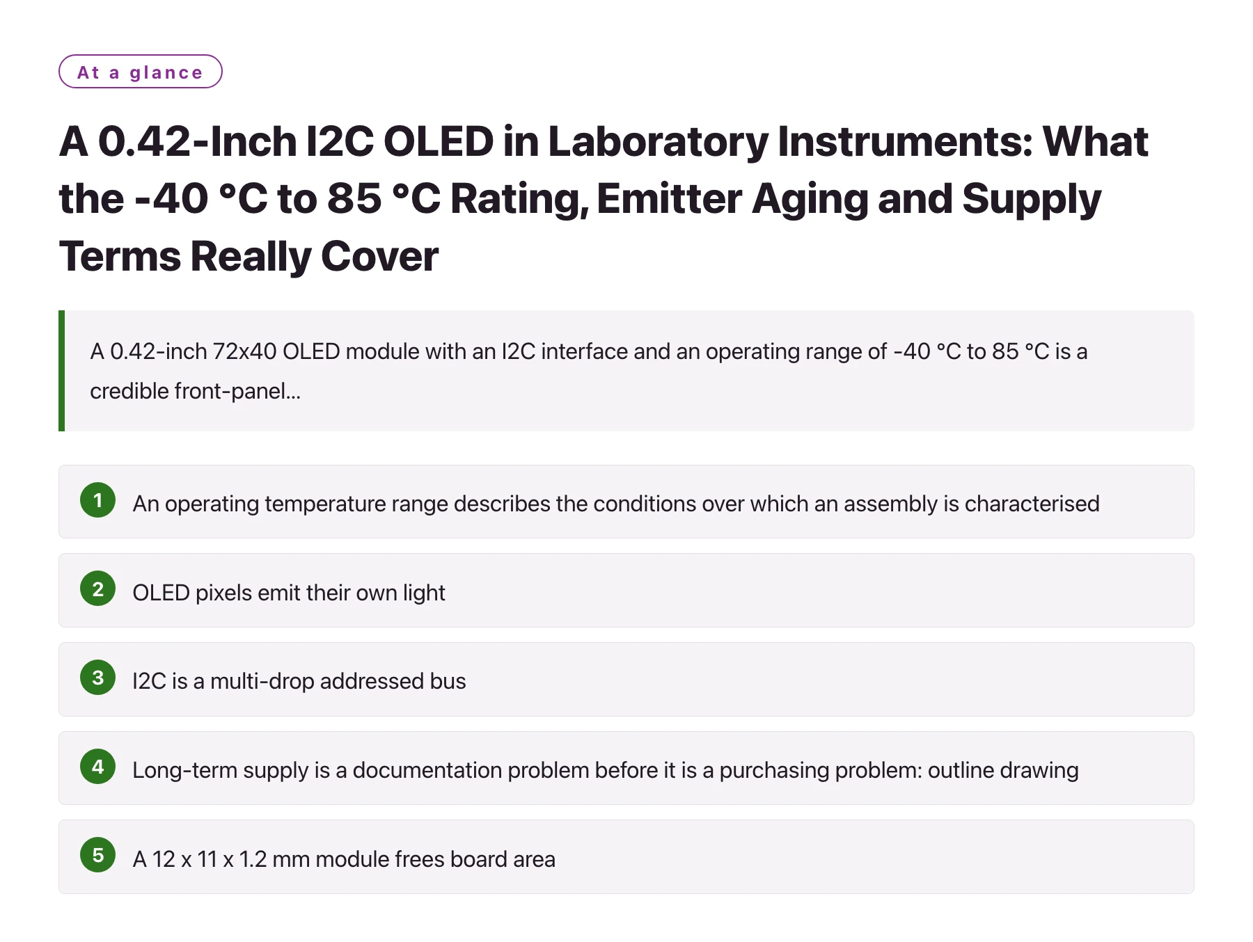
- An operating temperature range describes the conditions over which an assembly is characterised, so the engineering question is which conditions were tested - powered cold start, thermal cycling, or steady-state soak with the panel lit.
- OLED pixels emit their own light, so there is no backlight lamp or backlight driver to replace; the wear-out mechanism that matters is emitter aging and the brightness spread it eventually creates across a fixed layout. [1]
- I2C is a multi-drop addressed bus, so the display shares two wires with every other device on the board and has to be planned around address conflicts, total bus capacitance and pull-up sizing. [3]
- Long-term supply is a documentation problem before it is a purchasing problem: outline drawing, FPC pinout, controller family and initialisation sequence have to be frozen so a later revision can be diffed instead of reverse engineered.
- A 12 x 11 x 1.2 mm module frees board area, but that area still has to hold pull-up resistors, decoupling and the connector, so the layout budget is worth checking before the front panel is cut.
Laboratory instruments have an awkward combination of requirements. The front panel lives in a room that is climate controlled for the samples rather than for the electronics, the instrument may be shipped to a cold site or stored in a warm service cabinet, and the enclosure frequently contains a heater, a pump or a lamp driver that makes the local thermal environment worse than the ambient room. A small emissive display that keeps its contrast in a cold room is attractive precisely because it removes the backlight as a variable.
The module discussed here is a 0.42-inch graphic OLED at 72x40 pixels, driven by an SSD1315 controller over I2C, with low power consumption and an operating range of -40 °C to 85 °C in a 12 x 11 x 1.2 mm outline. That resolution is not meant for video; it is enough for a setpoint, a channel label, a status line and an error code, which is what most bench instruments actually need to put in front of a user.
This article works through the reliability and supply questions that class of module raises in laboratory equipment: how to read a wide temperature rating, why backlight hours are the wrong metric for an emissive panel, how to wire a shared I2C bus inside a noisy enclosure, and which documents to obtain before design-in rather than after the first service call.
Reading the -40 °C to 85 °C Rating Correctly
An operating temperature range states the conditions under which a module is specified to work, and it is not by itself a claim about reliability at the two endpoints. [2] The engineering question is how those endpoints were established: a storage-only soak, a powered cold start, a thermal-shock cycle count, or an accelerated aging test with the panel actively driven. These are different experiments and they produce different answers.
The thermal path of a 0.42-inch module is short, which is both an advantage and a trap. The panel, the SSD1315 controller die and the flexible circuit sit inside a 12 x 11 x 1.2 mm volume, and the flex is often the main route by which heat leaves the controller and enters the host board. If the module is bonded to a metal front panel, the panel becomes the heatsink; if it is mounted on standoffs behind a polycarbonate window, the controller runs closer to its own self-heating and to whatever the instrument radiates from below.
Two effects deserve separate treatment. The electrical effect is that controller timing, internal supply behaviour and bus levels shift with temperature, so a cold start at the bottom of the range with a marginal pull-up resistor is a classic source of intermittent bring-up failures. The optical effect is that OLED luminance and colour move with temperature, so a default brightness that looks right at 22 °C in the lab may look different on a cold morning. Ask for the temperature behaviour as a curve, then decide how much firmware compensation you are prepared to carry.
Neither effect is visible in a datasheet headline, so the practical rule is to test the module in the mounting concept you intend to ship, with the instrument's own heat sources running. A display that passes a chamber test on a bare breakout board can still fail once it is enclosed behind glass with a pump underneath it.
Ask for the evidence in a form you can act on: a test condition, a sample size and a curve, rather than a single number. A temperature range, a brightness figure and a supply statement only become useful once you know what was tested, on how many units, and at what drive current. Where those answers are unavailable, treat the requirement as unverified and plan a test of your own.
Cold start exposes weak margins first
Below freezing, a decoupling network that was adequate at room temperature can slow the I2C edges enough that the first transaction after power-up is lost. The fix is rarely the panel itself; it is usually a staged initialisation routine that re-arms the controller handshake, tolerates a missed acknowledgement, and does not assume that the first write after reset succeeded.
One board in a chamber is not a sample. Keep at least three units in the cold-start loop, include the slowest and fastest of them, and repeat the test after the instrument has been stored cold overnight rather than only after a short soak.
Write the mounting concept next to the temperature requirement in the specification; the same module can pass or fail the same rating purely on how it is attached and what sits beside it.
Where the Wear-Out Actually Happens on an Emissive Panel
Backlight lifetime is the familiar specification for LCD modules, because the light source is a separate component with its own degradation curve and, in some mechanical designs, a defined replacement path. An OLED module has no backlight at all: each pixel emits light when current flows through its own organic stack, so there is no lamp to dim with age and no backlight driver to fail. [1]
That does not remove aging, it relocates it. The emitters lose efficiency as they are driven, and because different regions of a fixed layout carry different average currents, the panel can develop a visible brightness spread over time: a status line that is lit continuously ages faster than the pixels around it. On a 72x40 panel this matters more than it would on a large screen, because the same field positions stay lit for the whole service life of the instrument.
The engineering response is behavioural rather than electrical. Keep the default brightness as low as the ambient light allows, blank or dim the panel when the instrument is idle, avoid leaving an inverse-video screen on all day, and avoid pinning the same label to the same pixels for years if the firmware can alternate or jitter its layout. Ask what drive current and what duty cycle the aging data was measured at, because a figure quoted at one current density does not transfer to your drive scheme without the curve behind it.
Reliability Questions to Put in Writing Before Design-In
| Topic | Question to ask | Why it changes the design | Evidence to request |
|---|---|---|---|
| Temperature | Was the -40 °C to 85 °C range verified with the module powered and the panel active? | A storage-only rating says nothing about cold-start behaviour of the controller, the internal supply or the bus | Chamber test report with drive conditions, dwell times and the number of units tested |
| Optical behaviour | How do luminance and contrast move across the operating range, and at what drive current? | Decides whether firmware needs temperature compensation or extra brightness headroom | Luminance versus temperature curve plus the measurement method |
| Interface | Which I2C address options exist, and what pull-up value was characterised for the bus? | Address conflicts and total bus capacitance determine whether the display can share the sensor bus | Datasheet timing table, module schematic and a reference layout |
| Mechanical | What are the outline, active-area and flex tolerances, and how should the module be attached? | Bezel clearance, window position and the thermal path all follow from those tolerances | Outline drawing with tolerances and the recommended mounting method |
| Supply | Which controller and which module footprint stay available, and what notice precedes a change? | An unplanned redesign three years into a ten-year instrument is expensive | Product change notification process and the current second-source position |
Each row should end up as either a test in your qualification plan or a clause in the purchase order, not as an unresolved item on a slide.
A Qualification Sequence That Fits a Small Front Panel
- Fix the address map and the bus budget first. Decide which device owns which address and how much bus time the display is allowed to consume before the schematic is frozen; retrofitting an address strap later usually costs a board revision.
- Run a cold-start matrix, not a single cold test. Power the instrument down overnight at the low end of the range, then bring it up repeatedly and log every failed handshake. Retry logic hides marginal hardware, so record the failures rather than the eventual success.
- Log optical drift over the first hours and days. Capture brightness and contrast at switch-on, after thermal stabilisation and after a long idle period, so that any firmware compensation you add is based on measured behaviour rather than on a guess.
- Test the panel where the electrical noise lives. Run the display while the pump, heater or lamp driver is switching. A shared I2C bus that is clean on the bench frequently shows occasional lost transactions inside the finished enclosure.
- Freeze the initialisation sequence in version control. Store the exact register writes, the timing between them and the panel variant they were validated against. That file is what makes a future module revision comparable instead of mysterious.
Wiring a Shared I2C Bus Inside a Noisy Enclosure
I2C is a multi-drop, addressed serial bus: every device listens on the same two wires and replies only to its own address, while the controller supplies the clock. [3] That simplicity is exactly why a small OLED integrates cheaply into an instrument, and it is also why a bench prototype can behave perfectly while the production unit does not.
Three things change once the bus leaves the bench. Total bus capacitance rises with cable length and connector count, which rounds off the rising edges and eventually corrupts transactions, so pull-up sizing becomes a system decision rather than a module decision. Switching noise from a pump or heater driver couples onto the two signal wires, which makes routing away from the power stage and keeping the return path short more important than the choice of panel. Address conflicts appear when two identical modules are populated from the same bill of materials, and the cure is a strapping option or a bus switch decided before layout.
Refresh strategy belongs in the same budget. In a laboratory instrument the text and setpoints change slowly, so the firmware should write only the pages of display memory that changed and leave the rest untouched; that keeps bus occupancy low and reduces the average current the panel draws. For a part in this class, the 0.42-inch I2C OLED graphic display offered by DisplayModule display modules is specified for low power consumption, and how much of that specification is realised in practice depends on how often the host chooses to write to it.
Treat the display as one more device on a shared bus with a limited time budget, and the electrical design stays simple even in a warm, noisy enclosure.
Long-Term Supply Is an Engineering Deliverable
Instruments are usually sold with a service life measured in years, and the display is one of the parts most likely to be replaced by its maker, because module vendors refresh controller families faster than instrument companies refresh products. Treat continuity as a design deliverable: record the exact module revision, keep a golden sample together with its measured brightness data, and archive the initialisation sequence beside the schematic so a future revision can be compared against a known reference rather than reverse engineered from a working unit.
Material compliance belongs in the same folder. Restrictions on hazardous substances determine what can be shipped and which paperwork accompanies the instrument, so the declaration for the module should be filed with the drawing at design-in instead of being chased when a customer audit arrives.
Decide the second-source policy before the first production run. If the panel is compatible only with itself, then either accept a redesign risk or qualify an alternative early, while the mechanical design is still fluid and a new flex footprint costs a drawing change rather than a service campaign. The cheapest moment to discover that a 72x40 module has a different pinout is during prototyping, not during a field replacement.
Sources
Frequently asked questions
Does the -40 °C to 85 °C rating mean the module is reliable at those extremes?
It means the module is specified to operate across that range, which is a statement about functionality rather than about long-term reliability at the endpoints. What matters for an instrument is how the endpoints were verified: powered cold start, thermal cycling, and how long the panel was driven at temperature. Ask for the test conditions and the sample size, then reproduce the worst case in your own mounting concept.
Why is backlight lifetime the wrong metric for an OLED front panel?
Because an OLED panel has no backlight; each pixel is its own light source, so there is no lamp or backlight driver whose degradation dominates end of life. The wear-out mechanism is emitter aging, which appears as a gradual luminance loss and as a brightness difference between heavily used and lightly used regions of the layout. Track average drive current and static content instead of watching a backlight hour counter.
Can the display share the I2C bus with the rest of the instrument?
Yes, I2C is a multi-drop addressed bus and the display is simply another device on it, but the shared bus has to be designed as a system. Check address conflicts, total capacitance including cables and connectors, and the pull-up value that suits the worst-case bus load, and route the two signal wires away from switching power stages. Verify the final combination under the noise conditions the instrument produces in normal use.
What should I document to protect long-term supply of a small OLED panel?
Freeze and archive the module revision, the outline and flex drawings, the exact initialisation sequence, and a golden sample with its measured brightness data. That package lets you diff a future revision instead of reverse engineering it, and it shortens qualification if the module has to be replaced. Agree in advance what notice you will receive before a change or an end-of-life announcement, and decide whether a second source must be qualified.